- Home
- Browse Catalog and Order Now
- Ready to Ship Blanks
- Made to Order Blanks
- Aluminum & Steel Custom Vice Jaws
- Metal Services
- Materials
- Company
- News
- Contact Us
When you request a prototype or production machining services, it is important to accurately call out the part specifications in your print. Incorrect information will result in a part that does not function as intended or extends your lead time as you and your contract manufacturer go back and forth to get the details right.
Parallelism and flatness are two of the most common areas of confusion customers run into, often mistaking one for the other. The following should help clear up any confusion.
First, let’s look at the basic definitions of parallelism and flatness:
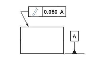
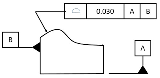
Parallelism describes the parallel orientation of one referenced feature of a part to a datum surface or line.
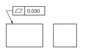
Flatness references how flat a surface is regardless of any other datums or part features.
When considering parallelism vs. flatness, imagining a table standing on a floor is helpful. If you carefully place a ball on the table, you may notice that the ball rolls across the table without you pushing it. Does this action indicate that the table surface isn’t flat? Not necessarily. The table surface could be entirely flat, but perhaps it was mounted to the table legs at a slight angle. In this case, the table and floor surfaces aren’t parallel to one another, causing the ball to roll.
Incorrectly calling out parallelism or flatness can compromise the cost and quality of your part, so it is essential to clarify what you are asking for. Parallelism is the correct callout when you are talking about how two different planes should relate to one another. Flatness is the proper callout when you are only referencing one surface and how flat that surface is relative to itself.
A DFM tip is to consider the number of surfaces your part will mount to. If multiple mounting surfaces are involved, you can view them as datums. Parts that mount to only one surface can have flatness callouts and parallelism callouts, while parts that mount to more than one surface should have parallelism callouts. Many people use these callouts interchangeably, they are not. In most cases, Flatness is more expensive than Parallel.
If you don’t call out flatness and parallelism in your print, dimensions will typically be held within the standard tolerances implied by the thickness of your material and the general tolerances of your part.
A simple alternative to calling out parallelism and flatness in your print is to call out the profile of the surface instead.
This specification describes the 3D tolerance zone around the surface of the part. Take the curved surface of a football, for example. A profile callout would specify that the entire surface where the radius is must fall within the tolerance zone. In many cases, profile callouts simplify measuring a part and still ensure your parts meet the specs needed for proper functionality.
Thank you to Reata Engineering and Machine Works for this content.
Sign up to receive our bi-monthly newsletter. Each issue includes industry ‘news you can use,’ special promotions, and announcements. Check it out, you can always cancel with a single click!
Call our sales team at 800-234-5613, or click below to submit your details. We’ll contact you immediately with a custom quote.